mipi
Reprinted from: http://ericnode.info/bus/mipi_csi_2/
This article briefly introduces the MIPI CSI-2 protocol and MIPI Alliance Specification for Camera Serial Interface 2 (CSI-2) described its protocol layers and application scenarios based on the official documents of the MIPI Alliance.
CSI (Camera Serial Interface) is a specification defined by MIPI, which is used to connect cameras and CPUs and transmit camera video signals. The latest specification is CSI-3 released in 2012, and the physical layer used is M-PHY. The CSI-2 specification to be introduced here was released in 2005 and uses D-PHY as the physical layer. DSI (Display Serial Interface) is also based on D-PHY. The difference is that it is mainly used by the host to transmit images to the display device.
In mobile phone applications, a general SoC will have at least two CSI Receiver controllers, which are used to connect the front and rear cameras respectively.
The following figure shows the physical connection of CSI-2:
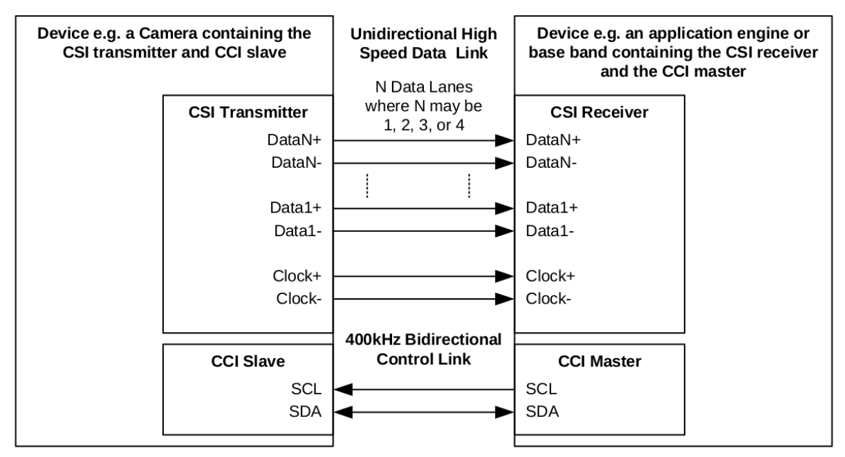
As you can see from the figure, the CSI-2 interface contains two connections: CSI and CCI.
CCI (Camera Control Interface) is a bidirectional connection and is compatible with the I2C protocol. This interface is mainly used to access the registers in the camera in order to configure and control it. Usually the host's I2C host controller is used, and the camera acts as an I2C slave device. Different manufactureras have different camera register layouts and field definitions.
The CSI interface is a one-way transmission, consisting of a clock lane and one to four data lanes to transmit image data. Adopts D-PHY physical layer protocol.
Like USB and Ethernet, complex protocols are generally layered to facilitate the dismantling of complex functions, implementation and verification one by one. The following figure shows the protocol stack of CSI-2:
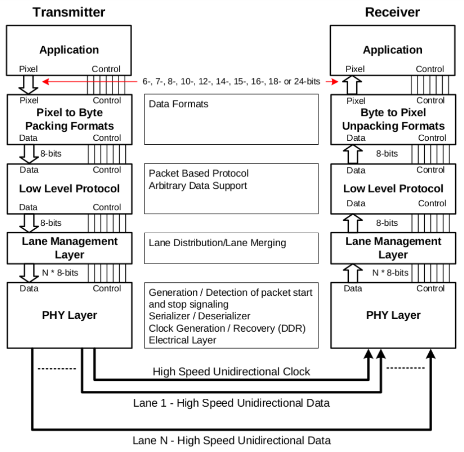
From top to bottom, they are:
- Application layer
- CSI protocol:
- pixel/byte conversion layer
- Low Level Protocol layer
- Lane Management layer
- physical layer
They are introduced separately below.
D-PHY physical layer
The physical layer defines the electrical characteristics, frame format, clock, etc. of the CSI transmission medium. As shown below:
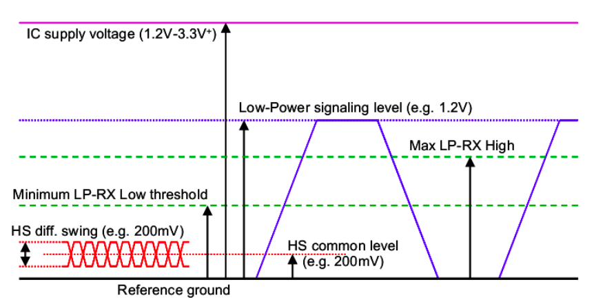
There are clock lane and data lane in CSI. Each lane includes two pins and transmits serial differential signals. The clock lane transmits the clock signal, and the receiving end samples the pin of the data lane according to the clock to obtain data.
D-PHY has two working states: low power (LP) and high performance (HS). In LP mode, it is in single-ended mode, and the signal transmitted is a single ended signal, which is usually used to maintain the connection; in HS mode, differential data signals are transmitted.
When transmitting data on the data lane, the SoT (start of transmission) signal is sent first, then the data payload is sent, and finally ends with EoT (End of transmission), which is a complete data packet on the physical layer. The receiving end identifies the data packet and obtains the payload through SoT and EoT, and then passes it to the upper layer for analysis.
Access and control of the physical layer are performed through PPI (PHY Protocol Interface).
Regarding the D-PHY specification, it is explained by the MIPI specification document MIPI_D-PHY_Specification.
CSI protocol layer
Above the physical layer is the CSI protocol layer, which consists of three layers, each with a clear function.
Pixel/Byte Packing/Unpacking Layer
In this layer, the sending end receives the pixel data from the application layer, packages it into byte format and sends it to the next layer; at the receving end, it unpacks the data from the LLP layer and transmits it to the application layer.
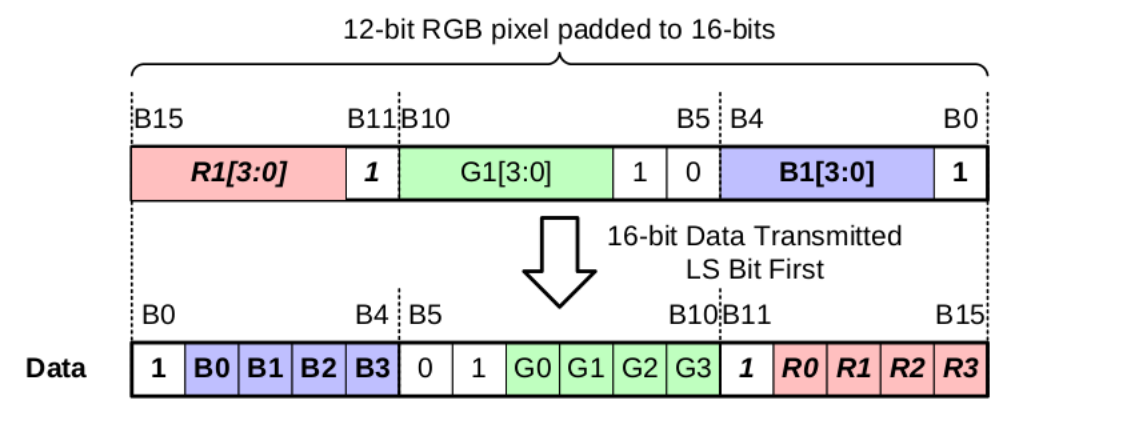
The main purpose of this layer is to convert different pixel formats (such as YUYV, RGBA, etc.) into 8-bit byte format, eliminate the differences between diffrent image formats, and reduce the complexity of transmission. For example, for RGB888 format, one pixel is 24 bits, which will be converted into three bytes for RGB565 format, one pixel is 16 bits, which will be converted into two bytes. For RGB444, the size is 12 bits, which needs to be converted into RGB565 format through padding, which is two bytes, as shown in the figure below:
Low Level Protocol
The Low Level Protocol (LLP) layer is the main functional layer of the CSI protocol. It not only defines the packet format, but also defines the synchronization mechanism used in transmission.
At the sending end, this layer is responsible for packaging the data transmitted from the upper layer, adding verification fields, adding synchronization packets, and sending it to the next layer; at the receiving end, it first verifies the integrity of the packet, parses each field, and executes it according to the packet type. Corresponding operation, transfer the image data to the upper layer.
The payload data processed bt LLP is converted pure byte data without the concept of pixels. By defining diffrent fields and packet types, the transmission of image data frames by frame achived.
Lane Management
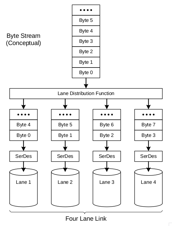
CSI-2 can be expanded using data lanes based on performance requirements. For different bandwidth requirements, the number of data lanes can be one, two, three or four. The sending end automatically distributes the data to each lane for transmission according to the number of lanes used; the receiving end recombines the data on each lane and restores the data.
This layer treats the packet transmitted by LLP as a piece of pure byte data and distributes it according to the number of lanes, regardless of the meaning of the data in the packet.
For example, for sending of 4 lanes, distribute it as follows:
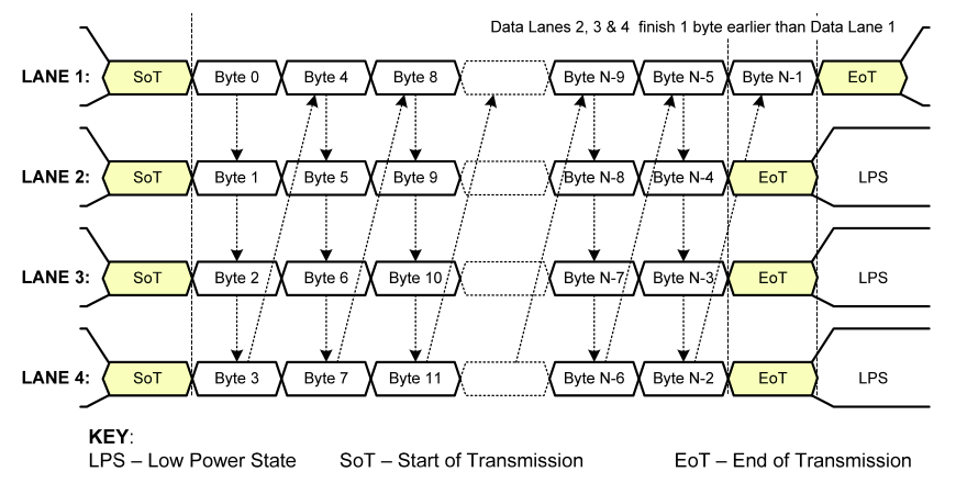
After such conversion, the transmission situation of a packet on the lane is as shown in the following figure:
From the above description, we can see that the pixel/byte conversion layer is used to eliminate pixel format differences and simplify transmission, and the lane management layer is used to distribute and splice packets and improve bandwidth. Both layers simply transform data and do not involve functional logic. The LLP layer is closely related to the transmission mechanism. Therefore, in the following discussion, the packet format displayed will only involve the LLP layer, ignoring the effects of the other two layers on the packet format, that is, directly displaying pixels without considering the conversion of pixels and bytes, and without considering the splitting of lanes. And display it directly on a lane, as shown in the figure below:
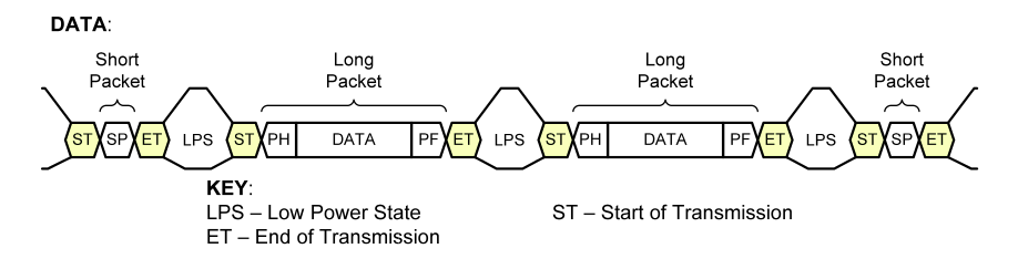
The picture above shows data transmission. The ST (SoT) and ET (EoT) with yellow background color are the packets added by the physical layer. Togather with the data packets in the middle, they represent a transmission. LPS is Low Power State, Dp-Dn is in low power consumption working state, and no data transmitted at this time. SP (Short Packet) and LP (Long Packet) are packets defined by the LLP layer and are used for synchronization and frame image data transmission.
Transfer a frame of image
As the implementation of the main function, LLP defines many packet types, fields and transmission mechanisms. This is not an exhaustive list of these details, but a description of the transmission format of a frame of image on the bus to give an intuitive and perceptual understanding. For details about the LLP, please refer to the agreement Chapter 9 Low Level Protocol.
There are two main types of LLP packets: SP (short packet) and LP (long packet). An LP contains one line of image data, and an SP is used for special purposes, mainly synchronization, such as indicating frame start (FS), frame end (FE), line start (LS) and line end (LE). Among them LS and LE are optional.
At the same time, the protocol stipulates that between each packet, there must be an LPS state, that is, packet spacing. Therefore, when transmittin SoT+SP+EoT, SoT+LP+EoT and LPS are transmitted on the bus.
A frame must start with an FS packet and end with an FE packet, with the number of frame height LP packets in the middle, each containing one line of image data. As shown below:
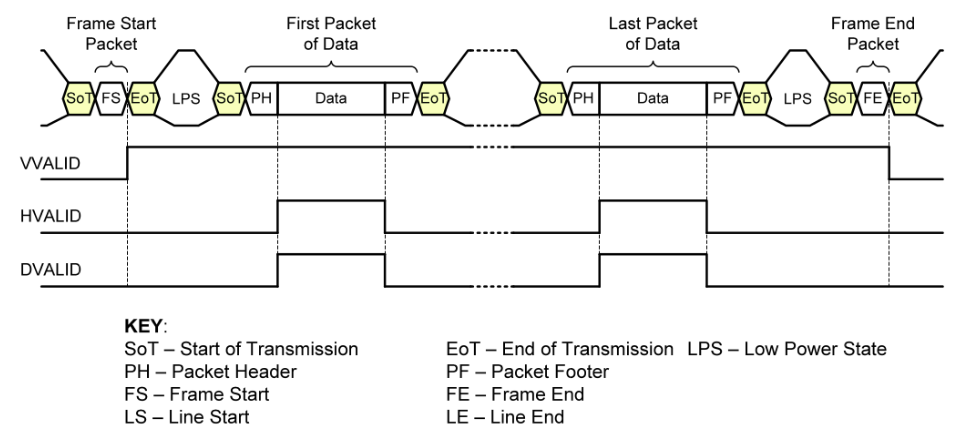
VVALID, HVALID and DVALID at the bottom of the figure indicate vertical and horizontal validity.
At the beginning of the transmission, the SP packet of type FS is first transmitted, indicating the beginning of a frame of image data and performing frame synchronization.
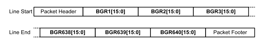
Then the image data is transmitted, one LP packet per line of data. Each LP packet consists of PH (packet header), Data and PF (packet footer). The definitions of each field are as follows:
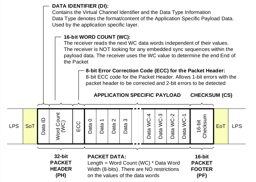
The content in the Data field is organized in different ways according to different image formats. This is the content of the Pixel/Byte conversion laye in the previous chapter. Regarding the format of Data, you can refer to it Chapter 11 Data Formats.
For example, the format of RGB565 is as follows:
After all the data packets of a frame of image are transmitted, an FE type LP packet is finally transmitted, indicating the end of a frame.
Linux driver
In a Linux system, to use CSI for image transmission, two additional drivers are required: CSI receiver driver and CSI sender driver.
The CSI receiver driver is used to control the CSI peripherals on the SoC, read the data on the CSI bus and output it to the memory or ISP. It is located in drivers/media/platform/soc_camera. On the one hand, the driver implements the structures and callback functions required by the soc_camera subsystem and the v4l2 subsystem, becoming a v4l2 device, which is exposed to the user layer through the /dev/video interface; on the other hand, it controls the CSI hardware in the SoC and calls its The subdev interface implements specific transmission.
The CSI sender driver, that is, the camera sensor driver, is located in drivers/media/i2c. On the one hand, the driver communicates with the sensor through I2C to configure parameters, start or stop image transmission; on the other hand, it implements the structure and callback functions required by the soc_camera subsystem, and as the subdev of the v4l2 device, provides an interface for the receiver driver to call.
Through the soc_camera and v4l2 subsystem frameworks, the sensor driver and host driver are independent of each other and can be reused.
Summarize
This article introduces the hierarchical structure of the CSI-2 protocol, shows the actual data transmission on the bus, and provides a perceptual understanding. The introduction to the driver is very simple and does not involve details, because the implementation details are related to the kernel version, and the v4l2 subsystem and soc_camera subsystem have also been evolving.
Unlike the I2C and SPI buses, the CSI bus requires a high-performance oscilloscope for online analysis due to its high speed. It is important to understand concepts to help when writing drivers.
©2023-2024 rculock.com